Ornithopter — Bio-Inspired Flapping Wing Drone
Fusion 360 · Crank-Rocker Mechanism · Composite Structure · University Funded
Bio-inspired aerial robot mimicking avian flight dynamics through flapping-wing actuation. Targeting stable flight and hover via lightweight composite structures and an optimised four-bar flapping mechanism. Currently in design and prototyping phase.
3D Model — Interactive
Project Objective
Design and develop a lightweight flapping-wing ornithopter capable of biologically inspired aerial locomotion using mechanical wing actuation instead of conventional rotary propulsion. The project explores how avian flight principles can enable quieter operation, improved maneuverability, and efficient low-speed flight for future compact UAV systems.
Bio-Inspired Flight Concept
The ornithopter architecture draws inspiration from natural avian flight mechanics, where lift and thrust are simultaneously generated through rhythmic wing flapping. Unlike fixed-wing aircraft that require forward velocity or multirotors relying on continuous high-RPM propellers, this system utilises oscillatory wing motion to achieve biologically efficient aerodynamic behaviour.
- →Flapping-wing locomotion inspired by small bird morphology
- →Target wingbeat frequency: 4–6 Hz
- →Low Reynolds number aerodynamic operating regime
- →Passive aerodynamic efficiency through unsteady airflow generation
- →Reduced acoustic signature compared to conventional quadrotors
Mechanical Transmission System
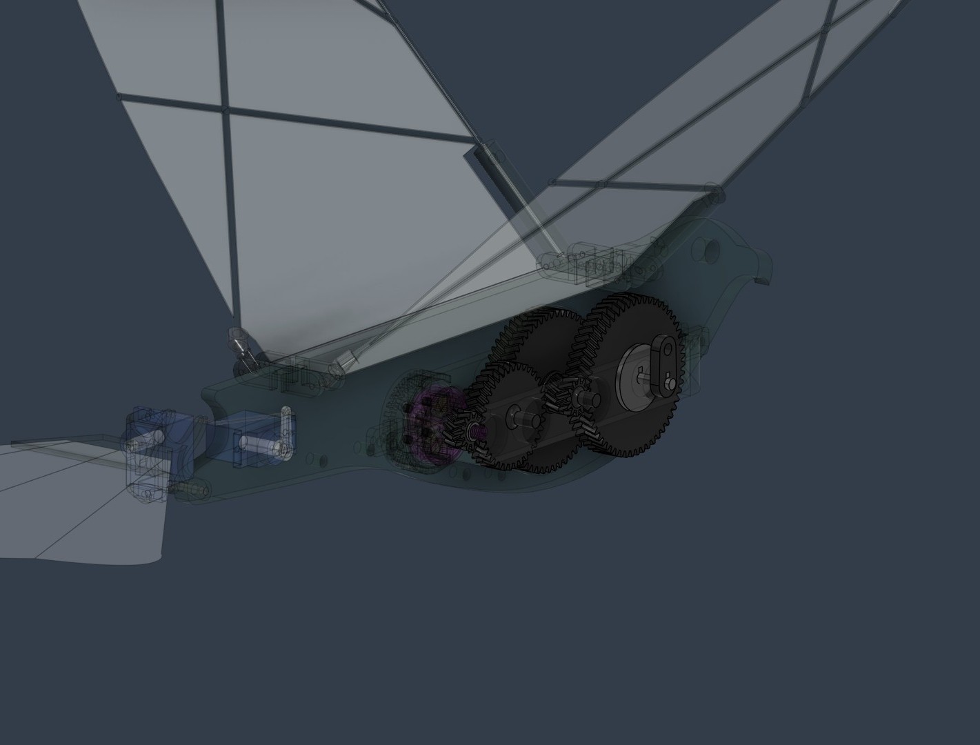
A crank-rocker four-bar linkage converts high-speed rotational motion from the brushless DC motor into controlled reciprocating wing motion. A custom 55:1 reduction gearbox was designed to reduce motor speed while amplifying torque required for sustained flapping actuation.
- →Crank-rocker four-bar mechanism designed using Grashof condition
- →55:1 reduction gearbox for high torque transmission
- →Helical gear architecture for smoother meshing and lower vibration
- →180° phase-offset wing motion for inertial balancing
- →PTFE-lubricated joints for reduced friction losses
Wing Architecture & Aerodynamics
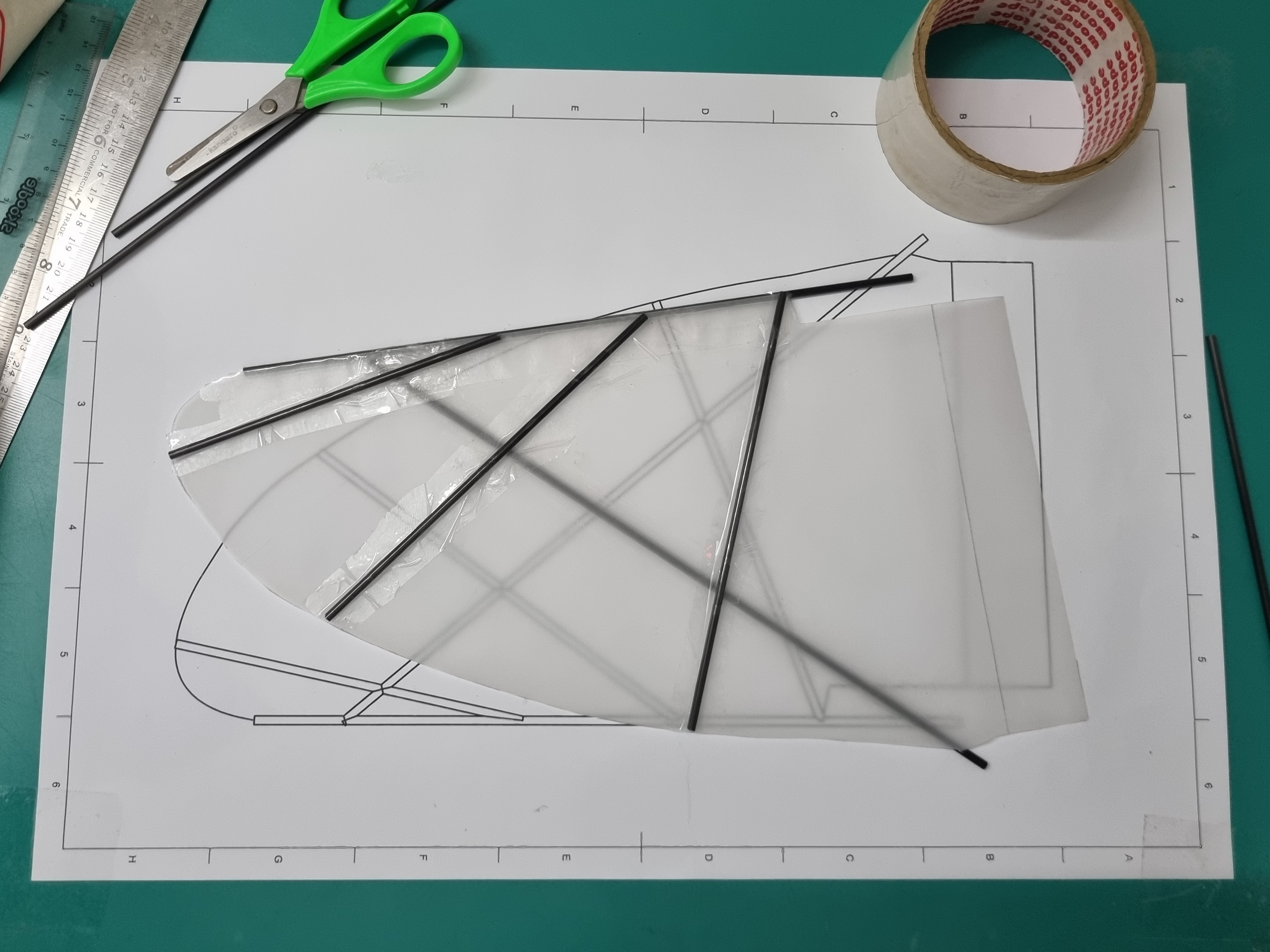
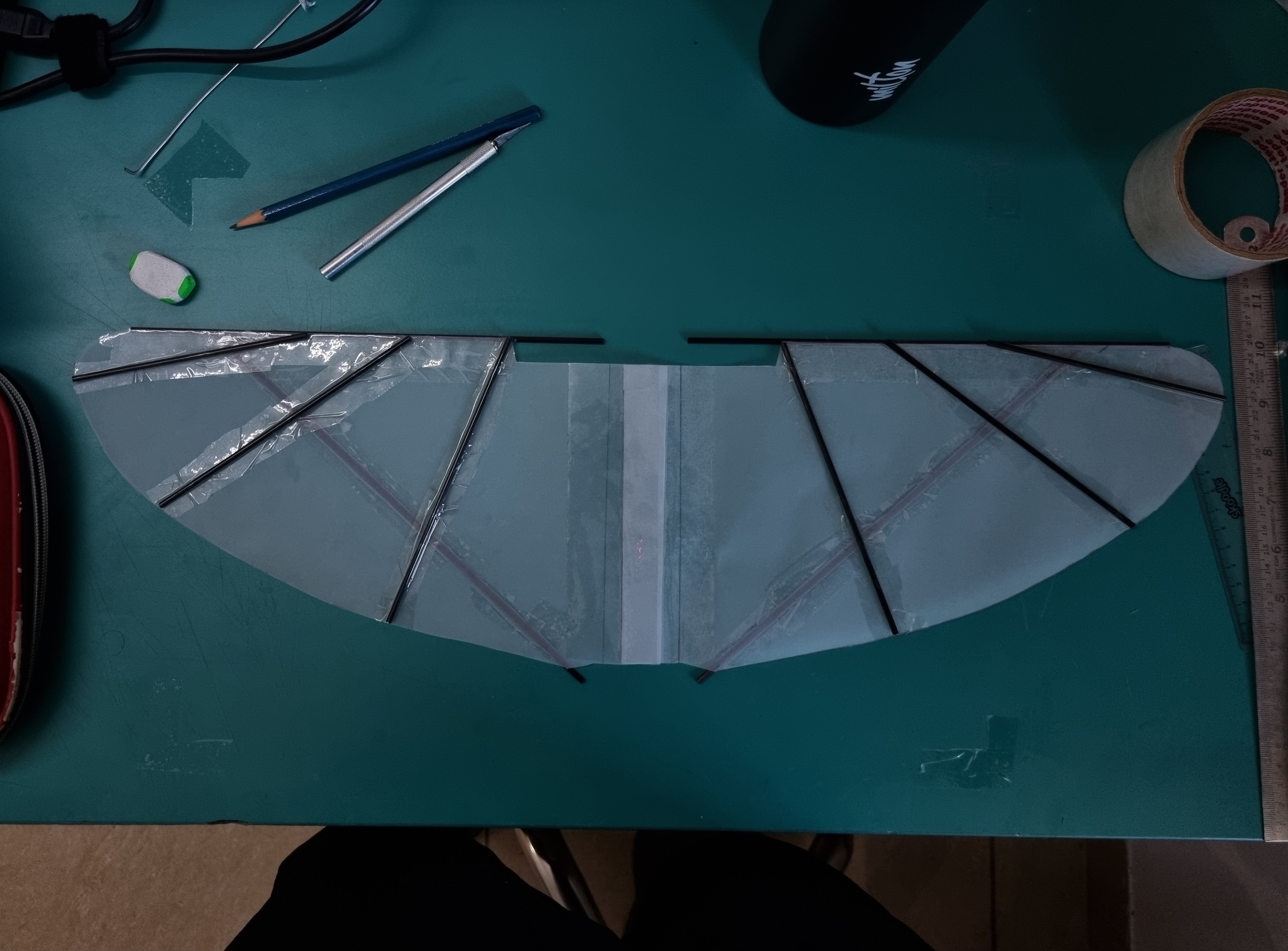
The wing system was engineered to maximise lift generation while maintaining extremely low structural mass. Carbon fibre spars provide bending stiffness, while lightweight membrane surfaces enable controlled aeroelastic deformation during the flapping cycle.
- →Carbon fibre leading spars for stiffness-to-weight optimisation
- →Mylar membrane wings for lightweight aeroelastic response
- →Wing geometry tuned for stable low-speed flight
- →Symmetric flapping configuration for balanced force generation
- →Large effective wing area for enhanced lift production
CAD Design & Simulation
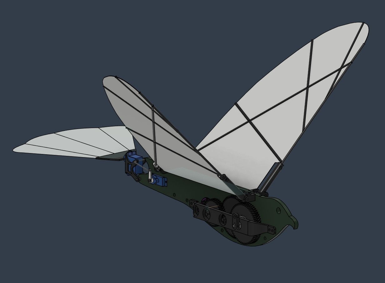
All structural and transmission components were designed in Autodesk Fusion 360. Motion studies and interference validation were performed to ensure smooth mechanism operation across the intended flapping cycle before physical fabrication.
- →Full assembly designed parametrically in Fusion 360
- →Motion simulation for linkage validation
- →Interference and clearance analysis for moving joints
- →Iterative geometry optimisation for weight reduction
- →Rapid design iteration enabled through modular CAD workflow
Fabrication & Materials
The prototype was primarily fabricated using additive manufacturing to enable rapid iteration and lightweight structural integration. Material selection prioritised stiffness, fatigue resistance, manufacturability, and low mass.
- →PLA+ structural frame for lightweight rigidity
- →PETG gears for improved wear resistance
- →FDM 3D printing for rapid prototyping
- →Press-fit shaft integration with miniature bearings
- →Modular assembly for simplified maintenance and redesign
Prototype Assembly
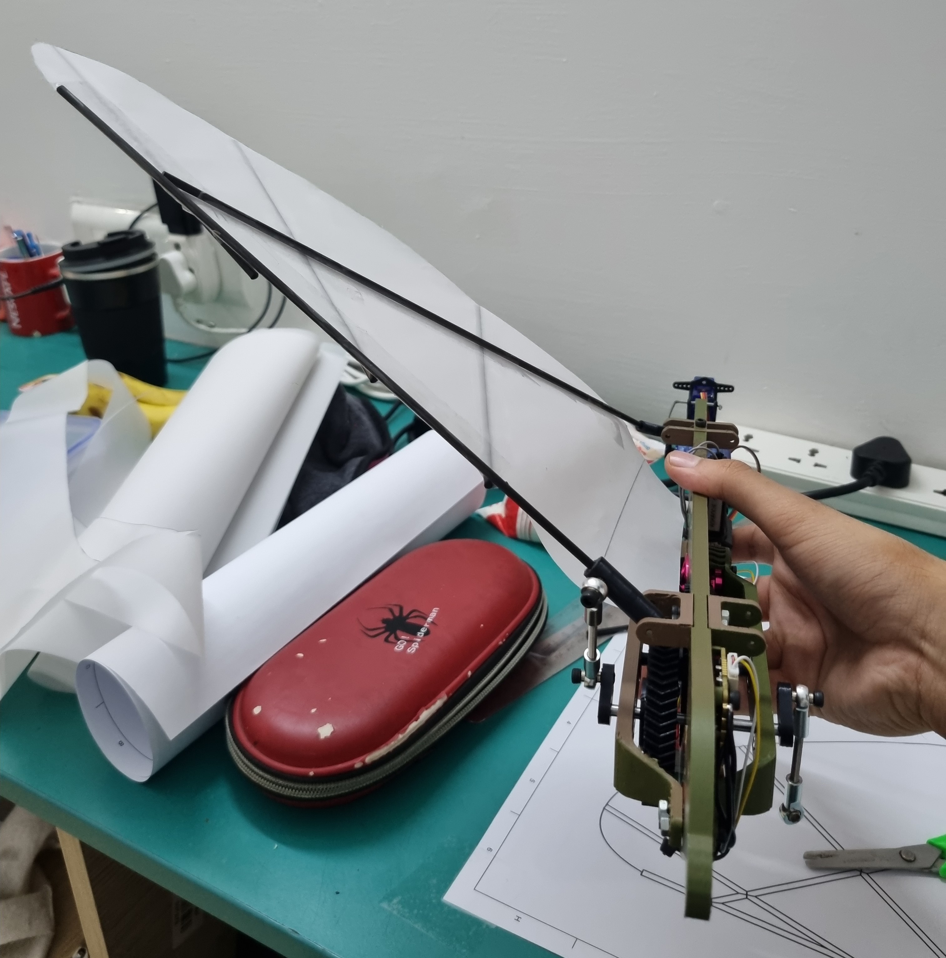
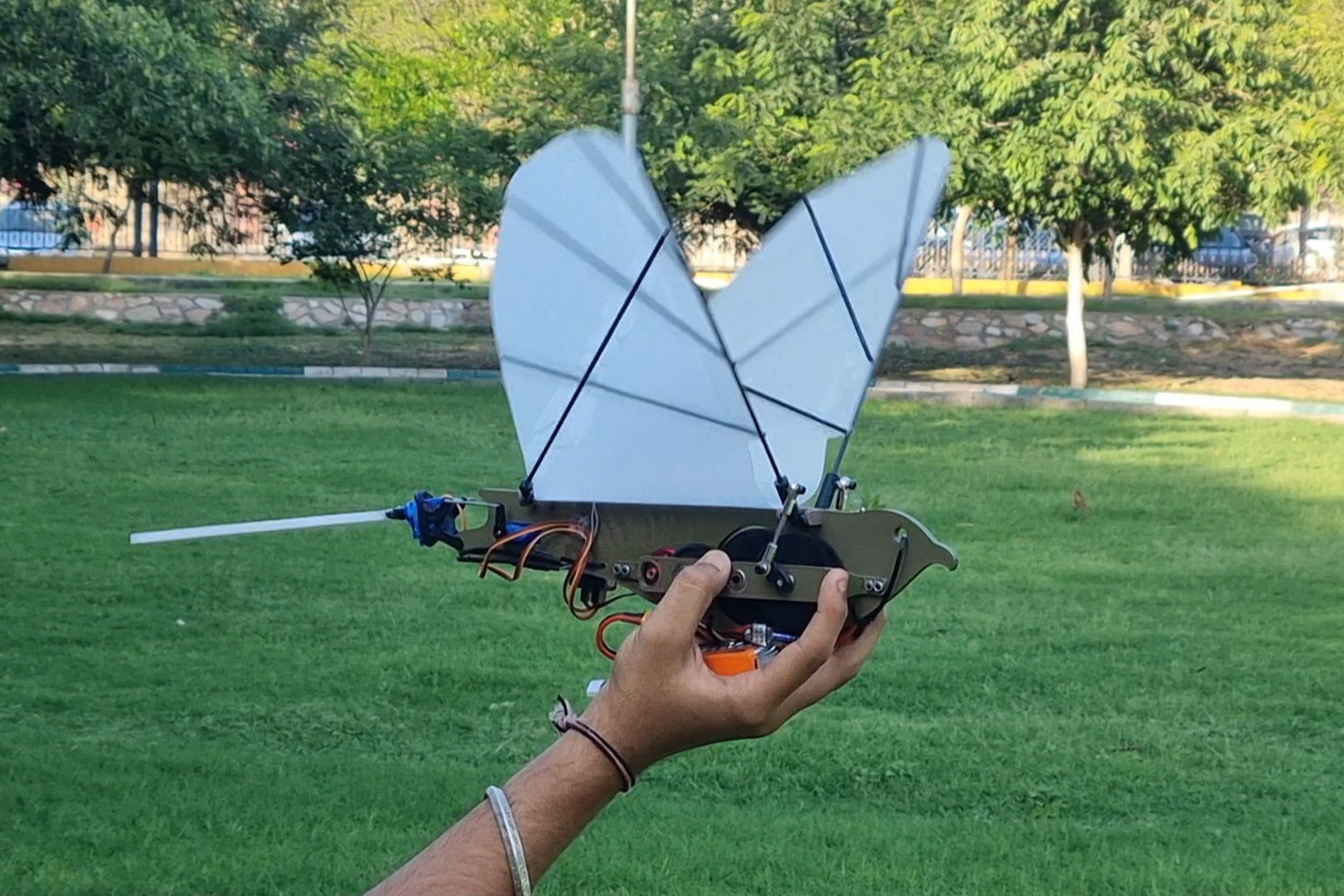
The final assembly integrates the gearbox, crank-rocker transmission, wing spars, membrane structure, motor system, and control electronics into a compact lightweight bio-inspired aerial platform.
- →Integrated drivetrain and flapping mechanism
- →Balanced dual-wing oscillation architecture
- →Compact embedded electronics layout
- →Modular structural access for rapid testing
- →Low-vibration mechanical integration
Testing & Performance Validation
Mechanical and structural testing validated drivetrain efficiency, wingbeat consistency, vibration behaviour, and structural durability under repeated flapping cycles. Bench testing confirmed stable oscillatory wing motion and reliable power transmission.
- →Stable wingbeat frequency maintained at 4–6 Hz
- →Mechanical transmission efficiency exceeding 85%
- →Frame deflection below 1 mm under operational load
- →Successful endurance testing over 1000+ flapping cycles
- →Reduced vibration through phase-offset wing motion
Engineering Challenges
The primary engineering challenge involved balancing lightweight construction with sufficient structural rigidity under cyclic aerodynamic loading. Additional complexity arose from choosing gear ratios and transmission mechanisms for efficient torque transmission, vibration minimisation, and synchronised flapping motion.
- →Reducing drivetrain losses at high reduction ratios
- →Maintaining structural stiffness under repeated oscillation
- →Balancing wing inertia for vibration reduction
- →Achieving low system mass without sacrificing durability
- →Synchronising dual-wing flapping dynamics
Future Development
Future iterations will focus on reducing total system mass, improving aerodynamic efficiency through CFD-driven wing optimisation and optimising gear and transmission mechanisms for higher efficiency and reduced weight.
- →CFD-based wing geometry optimisation
- →Lightweight material exploration for frame and gears
- →Efficiency improvements in gears and mechanical transmission
- →Free-flight testing and stability validation
- →Integration of IMU-based flight control
- →Wireless telemetry and remote control system
- →Adaptive wing morphing exploration
- →Autonomous flapping-flight stabilisation
Technical Specifications
Related Projects
Fixed Wing UAV
Custom Depron Foam Trainer Aircraft · Brushless Propulsion · Flysky RC
Smart Parcel Box
ESP32 · Fusion 360 · Barcode Auth · OTP · Theft Detection · Patented
Go-to-Goal Autonomous Mobile Robot
Arduino · MPU6050 · Polar Coordinate Control · Cascaded PID · Bluetooth